
b-1.jpg?width=1368&height=1340&name=Rail%20(175)b-1.jpg)


1.webp?width=500&height=380&name=HLL%20Overhead%20(661)1.webp)
.webp?width=640&height=429&name=pipe-rack-systems-1-1%20(1).webp)

A horizontal lifeline system (HLL) is a type of fall protection anchor system consisting of a flexible line (usually a steel cable or synthetic rope) secured horizontally between two or more anchorage points. This lifeline provides a continuous attachment for workers, allowing them to move freely over a work area at height while staying tied off, instead of being restricted to a single fixed anchor point. In other words, the worker's connection device attaches to a shuttle that glides along the horizontal line, so they remain secured even as they walk across an elevated area. These systems are sometimes informally called “fall protection cables” or “rat lines,” but the proper term is horizontal lifeline (HLL).
Horizontal Lifeline Systems
Custom and Pre-Engineered Lifeline Systems to Meet Your Application’s Needs
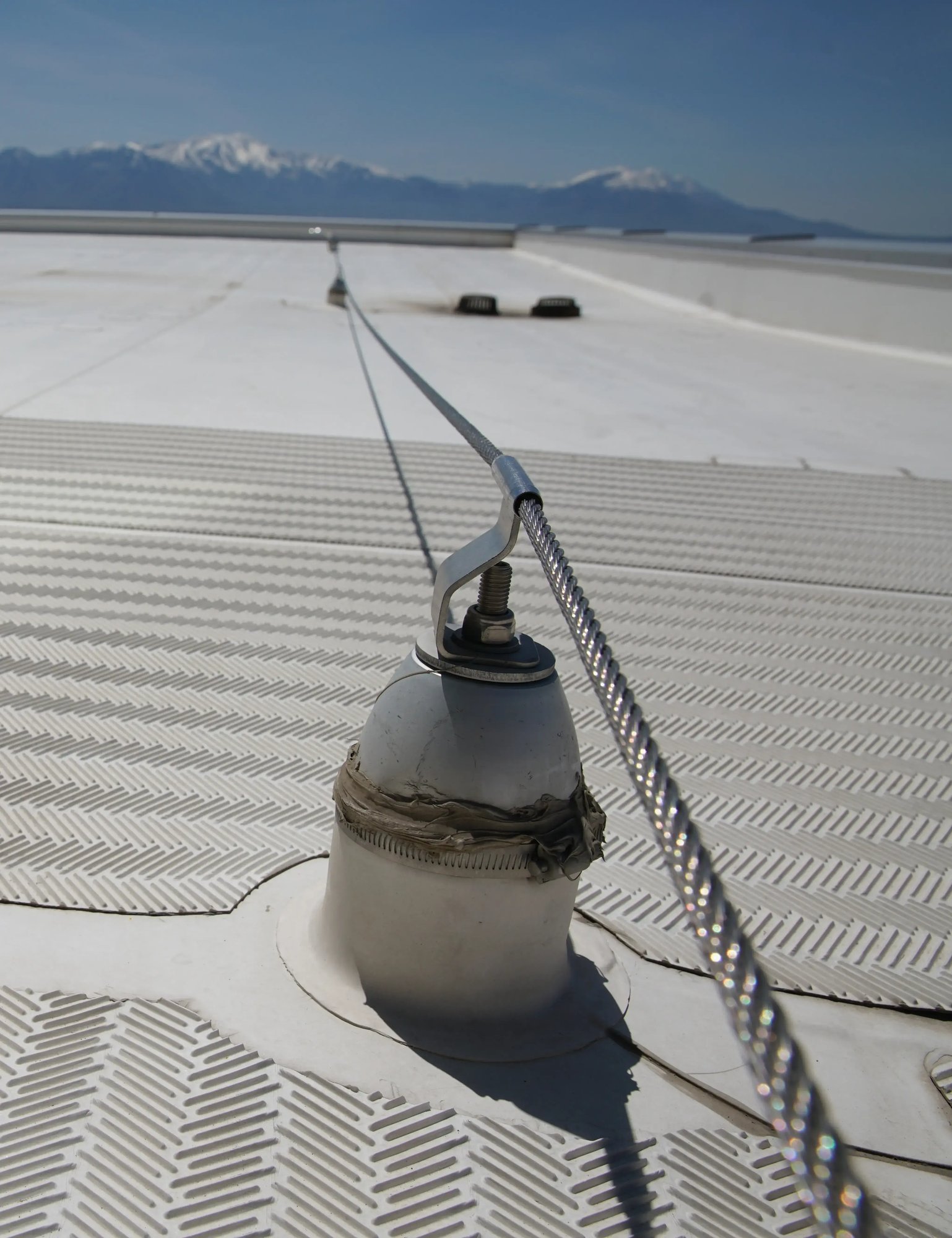
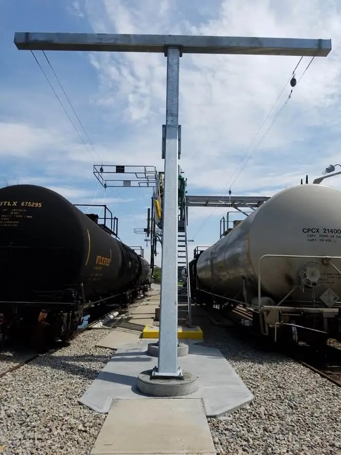
The horizontal lifeline consists of a cable attached to two or more anchor points on a rooftop, crane runway, bridge, or outdoor construction site, or any other elevated work area that poses a fall risk to personnel. A horizontal lifeline can be positioned at the base of the structure (e.g., a roof), overhead (e.g., a gallows style system commonly used for railcar and truck load/unloading applications), or somewhere in between these points (e.g., a crane rail application).
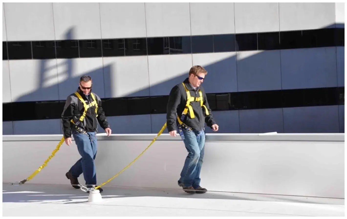
When used in combination with personal protective equipment, a horizontal lifeline can arrest a fall, limiting the amount of force that is transferred both to the worker and the fall arrest system. This same combination of horizontal lifeline, body harness, and lanyard can also serve as a fall restraint system, limiting the worker’s ability to move close enough to fall over an unprotected leading edge. The fall restraint and fall arrest properties of horizontal lifelines make the HLL an integral part of many fall protection systems.
System Types
Diversified Fall Protection a complete turnkey provider of OSHA compliant horizontal lifeline systems. Contact us for expert assistance with your fall arrest, fall restraint and fall protection requirements.
See Our Horizontal Lifelines

1-1.webp?width=2000&height=1520&name=HLL%20Overhead%20(661)1-1.webp)


Horizontal Lifeline FAQs
A horizontal lifeline system works by attaching the worker (wearing a full body harness) to a tensioned horizontal line, so that if the worker slips or falls, the system will arrest the fall and absorb the force. The lifeline is anchored at each end (and sometimes at intermediate points) to anchors capable of withstanding a minimum of 5000 pounds and often includes an inline energy absorber (shock absorber). If a fall occurs, the lifeline and its energy absorber will distribute and dissipate the fall forces across the anchors and the horizontal lifeline, which minimizes the impact force on the worker and the anchorage. This prevents serious injury by reducing the amount of force the user will feel, and thus likely resulting in less significant injuries. Horizontal lifelines can be used either in fall arrest mode (stopping a fall in progress as part of a personal fall arrest system) or in fall restraint mode (preventing the worker from reaching a fall hazard) depending on how they are installed and used. In all cases, the HLL provides a secure, continuous tie-off so the worker remains protected through their entire work area.
Horizontal lifelines are best used in situations where workers must work within a large elevated area and need continuous fall protection. Employers should consider an HLL whenever multiple workers need to work along an elevated edge or open area and free movement (without disconnecting and reconnecting their lanyards frequently) is required. For example, HLL systems are commonly utilized on construction sites, bridges, rooftops, and other maintenance or industrial sites where the work area is extensive. In such scenarios, other fall protection solutions like single-point anchors or guardrails might be impractical or overly restrictive. The decision to use a horizontal lifeline often comes down to the number of workers, the length of the work zone, and the nature of the task – HLLs offer a unique advantage of providing strong fall protection coupled with freedom of movement, which is ideal for tasks that require a high degree of mobility across the worksite. By using a properly designed HLL, workers can walk along beams, roofs, or other structures while remaining continuously protected from falls.
Horizontal lifeline systems offer several important benefits for worker safety and productivity:
- Continuous fall protection over a wide area: An HLL provides continuous tie-off, meaning workers don’t need to disconnect and reconnect as they move, unlike with single anchors. This constant protection significantly reduces the chance of a fall during transitions.
- Greater freedom of movement: Workers attached to a horizontal lifeline can move hands-free along the line and cover a larger work area, maintaining mobility and efficiency while staying safe. This is especially useful for long rooftops, loading bays, bridge girders, or anywhere a worker must travel some distance at height.
- Multiple workers on one system: Many horizontal lifeline systems are rated to protect two users at the same time, and specialized multi-span systems can accommodate even more, allowing a team to work together safely on the same line. This promotes teamwork and consistent protection for all personnel in the area.
- Enhanced safety compliance: Using an HLL helps ensure your operation meets or exceeds OSHA and ANSI fall protection requirements while keeping the focus on actual worker safety. In addition to regulatory compliance, the presence of a robust lifeline system builds a strong safety culture by actively preventing falls.
Overall, horizontal lifelines improve employee safety at heights by providing reliable fall arrest capability without unduly limiting the workers’ range of motion. They strike a balance between safety and practicality, enabling workers to perform their jobs efficiently while remaining protected from deadly falls.
Always refer to the manufacturer’s instructions and engineering guidelines for the exact capacity of your horizontal lifeline system, and never exceed the recommended number of users.
Most horizontal lifeline systems are designed to support two users at a time on a single span of lifeline. For example, one major manufacturer specifies that their temporary lifeline can be up to 60 ft long and safely accommodate a maximum of two workers simultaneously (one or two users on the line). Typically, each user is also subject to a weight limit (often around 310 lbs per person including tools and gear) to ensure the system can arrest a fall safely.
Allowing more than two people on one lifeline greatly increases the forces on the system, so additional users are generally not recommended unless the system has been specifically engineered for it. Some advanced permanent lifeline setups with multiple spans or specialized energy absorbers can handle more users – for instance, there are multi-span cable systems that allow “two users per span, up to six users per system” when properly configured. However, any increase in capacity must be verified by a qualified engineer and comply with the system’s design specifications. In practice, two workers per lifeline is the common safe limit unless documentation says otherwise.
Regular inspection and maintenance of a horizontal lifeline system is crucial for effective employee safety. Federal OSHA 1910 & 1926 require fall protection systems like HLLs be formally inspected at least once per year by a qualified individual or the organization's Competent Person. Many companies schedule comprehensive annual inspections by a trained safety professional or engineer to ensure the lifeline’s integrity. In addition, the system should be visually inspected before each use to catch any obvious issues (such as a damaged cable or a loose anchor) before workers connect to the system.
If a horizontal lifeline ever arrests a fall or shows signs of damage/wear, it must be removed from service immediately and not used again until it’s repaired or re-certified as safe. For example, if you notice a tension indicator has deployed (showing a shock absorber activated) or any part of the lifeline is bent, frayed, or corroded, stop using it right away. Below are some key things to look for during HLL inspections:
-
Anchors and hardware: Check all end anchors, intermediate brackets, bolts, and fittings for any deformation, cracks, looseness or corrosion. The anchor points should be solid and show no signs of failing or pulling out.
-
Lifeline cable or rope: Inspect the full length of the cable or rope for fraying, cuts, kinks, broken wires, excessive slack or stretching, or any kind of deterioration. Any damaged section of line is a serious hazard.
-
Connectors and components: Examine turnbuckles, shackles, carabiners, and trolleys/shuttles for wear, rust, or malfunction. Ensure any moving parts (like the shuttle that glides along the line) are intact and function smoothly.
-
Energy absorbers/indicators: If the system has an inline energy absorber or a visual impact indicator, verify that it has not been deployed or tripped (many systems have a tear-web or color indicator that shows if a fall force occurred). A triggered absorber or indicator is a sign the system experienced a fall and needs replacement or factory recertification.
-
Path and mounting: Confirm there are no new obstructions, sharp edges, or abrasive surfaces along the lifeline’s path that could damage it. Also, ensure any coatings or roof sealants around anchors remain intact to prevent leaks or structural damage
By diligently inspecting these systems on a regular schedule, you can catch problems early and ensure the horizontal lifeline will perform as expected to protect workers. Remember that maintaining the lifeline in good condition is as important as installing it correctly – a neglected HLL can become unsafe over time.
Because horizontal lifeline systems directly affect life safety, they should be designed and installed by qualified professionals. In fact, OSHA regulations require that HLL systems be “designed, installed, and used, under the supervision of a qualified person”. A Qualified Person in this context is typically a professional engineer or a safety expert with specialized training and experience in fall protection system design. This person has the expertise to analyze loads, select appropriate components, and ensure the system has an adequate safety factor for fall arrest.
In practical terms, a trained Competent Person (such as a certified safety supervisor or installer) may handle the physical installation of a pre-engineered horizontal lifeline kit on site, but the system’s configuration and anchor points should still be approved or certified by a Qualified Person (engineer). This means that the distances between anchors, the sag/tension of the cable, the anchorage strength, and the number of users are all reviewed by someone with the proper engineering knowledge. Having a qualified engineer design or sign off on the system is critical, because they will ensure the lifeline will support the required loads with the necessary 2:1 safety factor and account for dynamics of a fall on a horizontal lifeline system.
Attempting to install a horizontal lifeline without the input of a qualified professional is extremely risky – miscalculating the forces or using the wrong components could result in the system failing during a fall. To keep your employees safe, always involve a qualified fall protection engineer or a reputable fall protection company when setting up a horizontal lifeline system. Their expertise will ensure the system is not only compliant on paper, but truly effective in the field.